

H1/AS1 - 6th Edition
Welcome! This guide provides a overview of the Code Tools H1 Calculator - designed to help simplify H1 compliance. Before you begin, please ensure you're familiar with our Terms and Conditions and H1/AS1. Let's get started.
0.0
Key metrics are displayed below each building element, including
0.1
Each building element includes an R-value override option, which allows the user to enter a specific construction R-value sourced from third-party information. When this option is used, supporting evidence for the chosen R-value must be provided with any building consent application.

0.2
Only enter details for building elements that are part of your project. If there is no slab or suspended floor, just leave those inputs blank and they won’t be included in the calculation.
1.0
Enter the following details about your project: project name, author’s name, site address, and climate zone. See H1/AS1 - appendix C for climate zone definitions.

2.0
a)
Enable the ‘Embedded Heating’ option if applicable.

If ‘Embedded Heating’ is enabled and the slab R-value is below the minimum threshold, a warning message will appear.

b)
Select the slab type.

d)
Enter the area and perimeter length of the slab.

Both must be measured from the interior face of the walls at the perimeter of the conditioned space.

2.1
If the design includes underslab insulation, select the insulation R-value, then specify whether it extends under the entire slab or only as a 1.2 m perimeter strip.

2.2
a)
To define slab edge conditions, click ‘+ Edge Details’ to add an edge type

b)
Enter the total length for each edge type and select the properties that apply. If multiple edges share the same properties, combine their lengths and enter a single total under that edge type.

Note that any edge length not defined by the user will be assumed to have no insulation, no masonry rebate, and external walls with 90 mm framing.
The total length of all edge types combined must not exceed the perimeter length of the slab. If it does, a warning message will appear.

3.0
a)
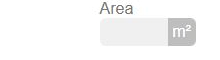
Enter the area of the suspended floor.
b)
Enter the R-value of the underfloor insulation.

c)
Select the appropriate framing specifications including joist size and spacing.

3.1
a)
If applicable, select the lining for the underside of the joists.

b)
If there is a lining, a still air space can also be included. Select the depth of the still air space as appropriate.

3.2
Select the enclosure type at the perimeter of the subfloor space.
If the subfloor enclosure type is ‘foundation wall’, enter the perimeter length of the subfloor.

3.3
Use these buttons to add and remove areas of suspended floor.

4.0
a)
Select the roof type.

b)
Enter the total area of the roof element (including any skylights, but excluding the eaves).

c)
Enter the R-value of the roof insulation.

A truss roof allows for two layers of insulation. Layer 1 sits at the bottom between the chords, and layer 2 is positioned on top, covering both the first layer and the chords.
d)
If the roof type is ‘Rafter’, select the appropriate framing specifications.

4.1
a)
Use these buttons to add and remove skylights.

b)
Enter the dimensions and R-value of each skylight.

4.2
Use these buttons to add and remove areas of roof.

5.0
Select the typical joinery specification. This will set the default R-value for all new joinery elements and update the R-value of existing joinery.

5.1
a)
Define the building’s wall types to calculate the construction R-value of each type.
Select if the wall type is external or internal.

b)
For external wall types:
i)
Select the cladding type. And enter the R-value of the wall insulation.

ii)
Then select the appropriate framing specifications.

c)
For internal wall types enter the R-value of the wall insulation. Then select the appropriate framing specifications.
5.2
Use this button to add further wall types.

6.0
a)
Enter the dimensions or total area of the wall (including any joinery).
The system will automatically calculate the net wall area by subtracting any joinery.

Or enter the total area of the wall (including any joinery).
The system will automatically calculate the net wall area by subtracting any joinery.

b)
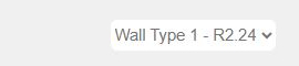
Then select the appropriate wall type from the drop down menu. The options of the drop down menu correspond to the wall types defined above in the wall construction section.
c)
The calculator allows users to enter each wall individually. Alternatively, if multiple (or all) walls share the same thermal resistance (R-value), their combined area can be entered as a single value.
6.1
Use these buttons to add and remove walls.

6.2
Use these buttons to add and remove joinery elements from the wall.
Joinery elements include windows and doors.

6.3
a)
Enter the dimensions of each joinery element.

Or enter the area of each joinery element.

If the total joinery area of the building exceeds 40% of the total building wall area a warning message will appear.

b)
If necessary, adjust the R-values of the joinery elements.
By default the R-value of each new joinery element will match the typical joinery specification selected above in the wall construction section.
Note that changing the typical joinery specification will update the R-value of all existing joinery elements.
c)
The calculator allows users to enter each joinery element individually. Alternatively, if multiple (or all) joinery elements share the same thermal resistance (R-value), their combined area can be entered as a single value.
d)
Joinery labels can be modified by the user.
7.0
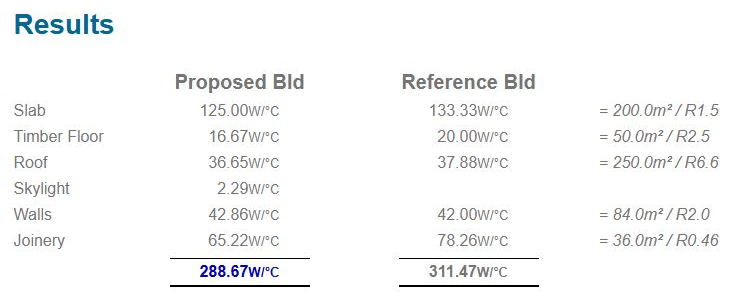
The energy loss of both the proposed building and the reference building are displayed in the results section.
Once all project parameters have been entered correctly, if the proposed building has a heat loss value less than the reference building the design is deemed compliant with Building Code requirement H1.2a, as per H1/AS1 Edition 5.
7.1
When complete the full report can be printed to include with your building consent application.

7.2
Enable the 'Background Graphics' option in the print settings to ensure your report displays correctly when printed.

We hope this tutorial has been helpful. If you have any questions or need further assistance, please email us at codetoolsnz@gmail.com.